How to Interface an Ultrasonic Sensor with an LCD Using a Microcontroller Dev Kit
Let's interface an ultrasonic sensor and a lighting system! In this project, we're going to design a system that uses an ultrasonic sensor to trigger a lighting system and an LCD as an information screen.
To show the system in action, we're making a non-contact garage parking sensor system using a C8051 microcontroller development kit and the Simplicity Studio IDE. The measured distance will be displayed on the LCD screen, and two LED floodlights will activate as a function of the distance between the vehicle and the sensor.
System Requirements and Applications
The system we're building here has the following features and requirements:
- Proximity/detection sensor: The ultrasonic distance sensor serves as a proximity/detection sensor. When an object is detected, it must constantly, in real time and with minimal time lag, measure the distance to a moving object.
- Small in size: The system should not occupy too much space in the garage or wherever else it is used, and it should fit within a reasonably sized enclosure.
- Bells and whistles, and/or lights: The system must have a noticeable alarm for announcing when an object has reached its ideal/targeted location.
- No AC voltage: It must be free of AC voltage (for safety and mobility reasons). Using 12 V as the supply voltage allows the system to run from an off-the-shelf AC-to-DC converter or from a 12 V battery.
Based on these parameters, you should be able to incorporate this system into a number of different applications:
- Swimming pool or home garden detection system for sending an alert when the curiosity of children and/or pets gets the better of them…like that never happens.
- To help prevent your friends and neighbors (or family members!) from stealing the leftover pizza and beer from your fridge—they are free to roam your kitchen, but if they get too close to the fridge…SOUND THE ALARM!
- Do you like to camp and enjoy the great outdoors? A battery-powered system could be used to help prevent your young children from getting too close to a stream when you’re reading your book or casting that fishing line.
At the end of this project, I'll show you a sensing system for a garage in action.
Let's get started by going through our bill of materials.
BOM
| Item # | Description / Source | Cost (each) | Other Information |
|---|---|---|---|
| 1 | C2400DK development kit | $148.75 | User guide (PDF) Quick-start guide (PDF) C8051F930 datasheet (PDF) Note: schematics are on pages 25-31 of the User Guide. |
| 2 | Breadboard | $8.98 | or equivalent |
| 3 | Jumper wire kit | $6.20 | or equivalent |
| 4 | Ultrasonic sensor | $29.99 | Datasheet (PDF) |
| 5 | N-Channel MOSFET | $1.17 | Datasheet (PDF) |
| 6 | 5V voltage regulator | $2.66 | Datasheet (PDF) |
| 7 | LED floodlight (qty 2) | $10.50 | 10W (12V DC or AC) |
| 8 | 10μF capacitor | $0.22 | or equivalent |
| 9 | 10μF capacitor (Tantalum) | $0.98 | or equivalent |
LCD Display
The LCD used in the project is part of the Silicon Labs CP2400DK development kit.
.jpg)
Figure 1. Silicon Labs CP2400DK development kit (C8051 microcontroller and LCD controller). Image courtesy of Digi-Key.
Refer to this article for information on the LCD and driver.

Figure 2. LCD screen with 16 segments for each of the eight digits (total of 128 segments). Image courtesy of Digi-Key.

Figure 3. 128-segment LCD driver. Images courtesy of Silicon Labs (pages 1 and 22).
Non-Contact Ultrasonic Distance Sensor
The PING (part # 28015) is a non-contact, ultrasonic (40kHz), distance measurement sensor made by Parallax.

Figure 4. Ultrasonic distance sensor. Image courtesy of Digi-Key.
The PING ultrasonic sensor is quite easy to use, and it only requires three electrical connections:
- 5VDC
- GND
- A digital signal referred to as SIG
With an advertised measurement sensing distance ranging from 0.8 inches (2 cm) to 118 inches (3 meters), this device works by first transmitting an ultrasonic burst and then providing an output pulse (on the "SIG" signal) that corresponds to the time required for the ultrasonic burst echo to return to the sensor. The distance to the target can then be calculated by measuring the echo pulse width. The image below helps describe this transmit-and-measure dance.
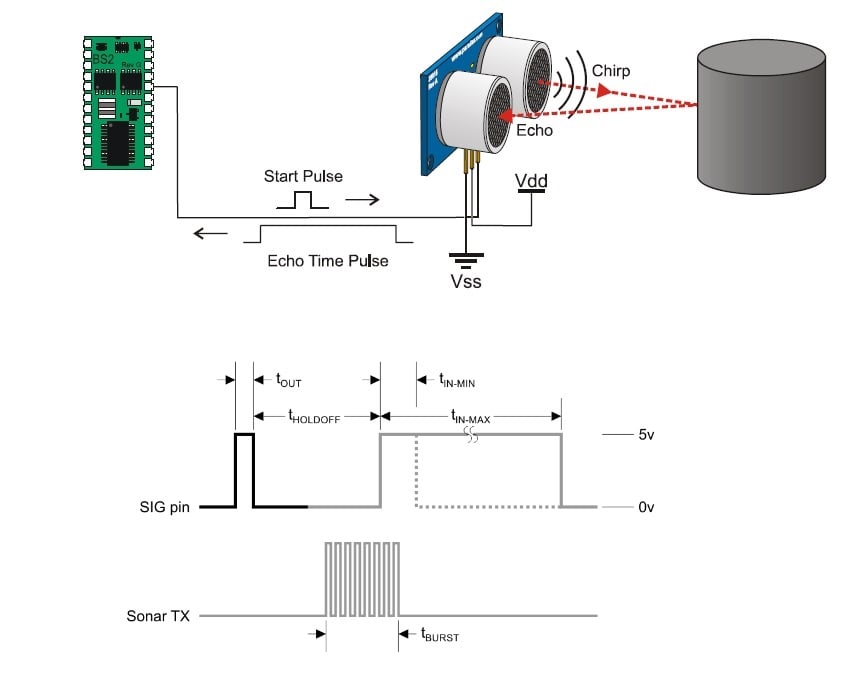
Figure 5. Ultrasonic distance sensor implementation and timing diagram. Image from this sensor datasheet (PDF).
And because this device uses sound for determining the distance to an object, one must be certain to take into consideration the air temperature when calculating the measured distance. As shown in the equation below, air temperature can significantly impact the measurement results.
LED Flood Lights
The reasons I chose these particular 12V LED flood lights are as follows:
- I had them in my lab.
- They are easy to mount using their built-in adjustable mounting bracket.
- They don't pull too much current (only 830mA each).
- They are IP65 rated, making them perfect for this project.

Figure 6. 12V LED Flood Light. Image courtesy of Amazon.
Voltage Regulator
Because the LED flood lights require 12 V (AC or DC) for operation, and because the PING sensor requires 5 VDC for operation, I decided to use a single 12 VDC power supply and then use a linear voltage regulator(LM1084IT-5.0 (PDF)) to generate the 5 VDC for the PING sensor; the microcontroller development kit will also use the 5V. Although the LM1084 series includes an adjustable-voltage variant, I opted for the fixed 5.0V version, which makes its implementation easier given that only two external components are needed, namely:
- a 10µF capacitor for the input voltage
- a 10µF capacitor (tantalum, as recommended by the datasheet) for the output voltage

Figure 7. LM1084 linear regulator. Diagrams from this datasheet (PDF).
N-Channel MOSFET
The N-Channel MOSFET (FQP19N20C (PDF)) is simply used as a switch for turning the LED floodlights on and off. Because this FET is rated for 19A (much more than the ~2A required to energize the two LED flood lights), it's obviously overkill. But hey, it was in my lab so I made use of it.

Figure 8. FQP19N20C N-channel MOSFET. Images from the datasheet (PDF).
Making the Connections / Schematic
SPI is used for communicating with the LCD driver. Figure 9 below shows the hardware configuration for the SPI module.

Figure 9. SPI configuration.
I've selected port P1.4 for communicating with the PING sensor (it both initiates the ultrasonic transmission, by sending a pulse to the PING, and then monitors the return signal); port P2.1 controls the LED floodlights.

Figure 10. Connection diagram. Click to enlarge.
Configuring the Microcontroller Development Kit
Prior to powering up the microcontroller development kit, after all the connections have been made, be sure to configure it as follows:
Jumpers:
- J11: VBAT to WALL_PWR
- J12: VDD to VIO
- J17: VBAT_PIN to VBAT
Switches:
- SW4: set to "2 CELL"
- Power switch (SW5) to "OFF" position
Cables:
- Connect the ribbon cable debug adapter to J9
- Connect the USB debug adapter to your PC
- Apply 5.0 VDC to connector P2
Example Application: Parking Sensor System
Now that we've designed our system, let's use it.
The Firmware
The code that controls the LED flood lights uses the following conditions:
- If the vehicle is greater than or equal to 97 inches from the sensor the lights are OFF.
- If the vehicle is less than 97 or greater than 30 inches from the sensor, the lights flash.
- If the vehicle is less than or equal to 30 inches from the sensor, the lights are ON.
Note: There's 1 inch of hysteresis built-in between 97 and 96 inches, and again between 31 and 30 inches.
                    //-----------------------------------------------------------------------------
// Display Value Routine
// ----------------------------------------------------------------------------

if(DisplayResults == 1)
{
 // Serial port.

 // Note: the format "%3.3f" --> "3" = width of 3 positions; ".3" = 3 digits after decimal point;
 printf("\nDistance: %3.3f inches          ", (float) MeasuredDistanceInches);

 // Set cursor to home position on screen.
 printf("\033[0;0H");

 MeasuredDistanceInches = MeasuredDistanceInches*10.0;

 // Note: the format "d" --> "0" = Left-pads the number with zeroes (0) instead of spaces.
 // "4" = width of 4 positions; "d" = Signed decimal integer.
 sprintf(display_string, "d in ", (unsigned int) MeasuredDistanceInches);

 LCD_OutString(display_string); // Send data to LCD.
 DisplayResults = 0;  // Reset flag.

 // If the measured distance is less than 30 inches, then turn ON the lights.
 if(MeasuredDistanceInches <= 300)
 {
  LightsOn = 1;
  LightOnFlag = 1; // Set flag signifying that the lights are ON.
  LightOffFlag = 0; // Set flag signifying that the lights are not OFF.
  LightBlinkFlag = 0; // Set flag signifying that the lights are not blinking.
 }

 // If the measured distance is less than or equal to 96 and greater than or equal to 31 inches,
 // then blink the lights.
 else if((MeasuredDistanceInches <= 960) && (MeasuredDistanceInches >= 310))
 {
  if((LightsOn == 1) && (LightBlinkCounter == 0))
  {
   LightsOn = 0;
   LightBlinkCounter = 1;
   LightOnFlag = 0; // Set flag signifying that the lights are not ON.
   LightOffFlag = 0; // Set flag signifying that the lights are not OFF.
   LightBlinkFlag = 1; // Set flag signifying that the lights are blinking.
  }

  else if((LightsOn == 1) && (LightBlinkCounter > 0))
  {
   LightBlinkCounter--;
  }

  else if((LightsOn == 0) && (LightBlinkCounter == 0))
  {
   LightsOn = 1;
   LightBlinkCounter = 1;
  }

  else if((LightsOn == 0) && (LightBlinkCounter > 0))
  {
   LightBlinkCounter--;
  }
 }

 // If the measured distance is less than 97 inches and greater than 96 inches,
 // and the lights are currently off, then leave the lights off.
 else if((MeasuredDistanceInches < 970) && (MeasuredDistanceInches > 960) && (LightOffFlag == 1))
 {
  LightsOn = 0;
  LightOnFlag = 0; // Set flag signifying that the lights are not ON.
  LightOffFlag = 1; // Set flag signifying that the lights are OFF.
  LightBlinkFlag = 0; // Set flag signifying that the lights are not blinking.
 }

 // If the measured distance is less than 97 inches and greater than 96 inches,
 // and the lights are currently blinking, then leave the lights blinking.
 else if((MeasuredDistanceInches < 970) && (MeasuredDistanceInches > 960) && (LightBlinkFlag == 1))
 {
  LightOnFlag = 0; // Set flag signifying that the lights are not ON.
  LightOffFlag = 0; // Set flag signifying that the lights are not OFF.
  LightBlinkFlag = 1; // Set flag signifying that the lights are blinking.

  if((LightsOn == 1) && (LightBlinkCounter == 0))
  {
   LightsOn = 0;
   LightBlinkCounter = 1;
   LightOnFlag = 0; // Set flag signifying that the lights are not ON.
   LightOffFlag = 0; // Set flag signifying that the lights are not OFF.
   LightBlinkFlag = 1; // Set flag signifying that the lights are blinking.
  }

  else if((LightsOn == 1) && (LightBlinkCounter > 0))
  {
   LightBlinkCounter--;
  }

  else if((LightsOn == 0) && (LightBlinkCounter == 0))
  {
   LightsOn = 1;
   LightBlinkCounter = 1;
  }

  else if((LightsOn == 0) && (LightBlinkCounter > 0))
  {
   LightBlinkCounter--;
  }
 }

 // If the measured distance is less than 31 inches and greater than 30 inches,
 // and the lights are either currently on or off (off would occur at startup), then leave/turn
 // the lights on.
 else if((MeasuredDistanceInches < 310) && (MeasuredDistanceInches > 300) && ((LightOnFlag == 1) ||
 (LightOffFlag == 1)))
 {
  LightsOn = 1;
  LightOnFlag = 1; // Set flag signifying that the lights are ON.
  LightOffFlag = 0; // Set flag signifying that the lights are not OFF.
  LightBlinkFlag = 0; // Set flag signifying that the lights are not blinking.
 }

 // If the measured distance is less than 31 inches and greater than 30 inches,
 // and the lights are currently blinking, then leave the lights blinking.
 else if((MeasuredDistanceInches < 310) && (MeasuredDistanceInches > 300) && (LightBlinkFlag == 1))
 {
  LightOnFlag = 0; // Set flag signifying that the lights are not ON.
  LightOffFlag = 0; // Set flag signifying that the lights are not OFF.
  LightBlinkFlag = 1; // Set flag signifying that the lights are blinking.

  if((LightsOn == 1) && (LightBlinkCounter == 0))
  {
   LightsOn = 0;
   LightBlinkCounter = 1;
   LightOnFlag = 0; // Set flag signifying that the lights are not ON.
   LightOffFlag = 0; // Set flag signifying that the lights are not OFF.
   LightBlinkFlag = 1; // Set flag signifying that the lights are blinking.
  }

  else if((LightsOn == 1) && (LightBlinkCounter > 0))
  {
   LightBlinkCounter--;
  }

  else if((LightsOn == 0) && (LightBlinkCounter == 0))
  {
   LightsOn = 1;
   LightBlinkCounter = 1;
  }

  else if((LightsOn == 0) && (LightBlinkCounter > 0))
  {
   LightBlinkCounter--;
  }
 }

 // If the measured distance is more than or equal to 970 inches, then turn OFF the lights.
 else if(MeasuredDistanceInches >= 970)
 {
  LightsOn = 0;
  LightOnFlag = 0; // Set flag signifying that the lights are not ON.
  LightOffFlag = 1; // Set flag signifying that the lights are OFF.
  LightBlinkFlag = 0; // Set flag signifying that the lights are not blinking.
 }
}
All the code for this project can be downloaded from the link below.
Building and Loading the Code, Testing the System
After downloading, building, and loading the code, I moved the entire system, including my benchtop DC power supply, to my garage for actual "in-field" testing (see video below). And I'm happy to report that the system worked as designed, and I didn't back into the rear wall/shelving of my garage!

Figure 11. The breadboard/system is energized and functional. Click to enlarge.
Next Steps for Making a Real Product
The next steps for this project would include:
- Integrating all the electronics into a custom-designed PCB.
- Adding a temperature sensor so that the system can determine the measured distance more accurately.
- Implementing, via firmware, a timer routine for turning off the LED lights after the vehicle is safely parked. After all, we don't want to waste electricity by keeping the lights on whenever the car is in the garage.
- Placing the custom-designed PCB in a suitable electronics enclosure.
- Replacing the benchtop 12V power supply with an OTS (off the shelf) 12V power adaptor, such as this one, and making sure its ampacity is adequate for powering the LED floodlights.
- Additional testing in both hot (100°F) and cold (0°F) environments.
Happy parking!
No comments:
Post a Comment